Building a simple RF-based sensor network
Background
I wanted to build a simple wireless sensor network where I could deploy small environment sensors around the house. The sensors needs to be cheap and low-power (so they could run off a small battery for at least a year). The sensors would broadcast their readings periodically back to a receiver which would be connected to my network so that I could collect, analyse and graph the data.
There are a few interesting problems in setting up such a network using low-cost hardware, which I thought I’d share.
RF communications
I wanted the sensors to be cheap, so using technology like Zigbee or Bluetooth wasn’t appropriate. I chose some simple RF transmitters and receivers that use the ISM band (in Australia, that is around 433MHz). This is the same band that is used by garage door openers, remote controls, car remotes etc. You can get these fairly easily on the internet under part names such as TXC1 (transmitter) and RXN3 (receiver). In my case, they are stocked by the local Jaycar shop as:
- Transmitter: http://www.jaycar.com.au/productView.asp?ID=ZW3100
- Receiver: http://www.jaycar.com.au/productView.asp?ID=ZW3102
If you source your own, you need to make sure that they are legal for your part of the world (i.e. they transmit on an acceptable frequency and they do not transmit too much power).
These transmitters use a simple On-Off Keying (OOK) encoding, which means that they transmit the carrier for a digital 1 and nothing for a digital 0. These devices have a single digital I/O line for the data, which makes them ideal to hook up to a small microcontroller.
How to use these devices
You might think that your problems are solved and you just need to send some digital data on the transmitter’s data input line and it will pop out receiver’s data output line, and you can do whatever you want with the message. Unfortunately, it is not quite that simple. Because these devices are comparatively simple in functionality, you will need to do some work on both the sending and receiving sides, in order to get reliable communications. Let’s cover the issues in turn.
Receiving reliable digital data
You might think that when no data is being transmitted that the receiver will just present a zero-value on its digital output line. However, the receiver has an Automatic Gain Control (AGC) circuit inside, and in the absence of any signal it will just amplify whatever noise is received by the RF stage and send that to the Analogue-to-Digital Converter (ADC). In practice, this means that when no signal is being transmitted the output from the receiver will be a stream of random data. This is not a problem during actual data transmission, because the AGC will adjust to the much stronger levels of the signal and the noise will be below its detection threshold.
The implications of this are twofold. Firstly, the software that reads the data from the receiver needs to deal with the fact that it will see random data when nothing is transmitted. It needs to be able to tell the difference between this random data and an actual message.
Secondly, the transmitter needs to give the receiver’s AGC a chance to adjust to the received signal levels. One way to do this is to prefix each message with a string of 010101… data. By the time the actual message is sent, the AGC should be tuned to match the received signal strength and the receiver should be relatively immune to noise. A corollary of this is that the message should not contain a large sequence of zero bits; otherwise the AGC may start tuning into the background noise again.
Where do the bits start and end?
Unlike communications using something like SPI or I²C the transmitter and receiver do not share a common clock signal. Depending on the hardware, the frequencies of the clocks on the transmission and receiving sides may differ by a significant amount, and even if they are very close there is no way for the receiver to know exactly when each bit is being sent.
As the receiver can only see the data bits, it needs to synthesise a transmitter clock by looking at the transitions between zero and one bits in the received data stream. The preamble I mentioned above is a good place to determine the clock frequency and offset, but it is also usually necessary to use the bit transitions within the message to ensure that there is no clock drift. This is only possible if the message contains a reasonable number of bit transitions. If, for example, a message contains a string of zero bytes, then there would be no transitions for the receiver to synchronise with, and there would be a risk that the receiver would lose track of the bit locations in the message data stream. One solution to this is to choose an encoding scheme that ensures that the message contains plenty of zero-one bit transitions regardless of what the message contains. The simplest such scheme is called Manchester Coding. This scheme encodes a zero-bit as a 01 bit pair and a one-bit as a 10 bit pair. Every data bit in this scheme contains a bit transition in the middle, and this gives the receiver a perfect way to extract the clock from the data.
Of course, Manchester Coding means that our message now takes twice as many bits to transmit as are in the message, but for this kind of application that is not important. There are other ways of encoding data that do not have such an overhead. For example, 8b/10b encoding uses 10 bits to encoding every 8-bit byte, while also guaranteeing that there are no more than 5 consecutive zero or one bits in the data stream.
Now that every data bit is transmitted either a 01 or 10 bit pair, there will be a level transition in the middle of each bit. As long as we can detect this transition point in the receiver we will be able to recover data bits without drifting out of synchronisation with the transmitter. I talk a bit more about an algorithm for implementing this detection further down.
Where are the byte boundaries?
Given the above, we can receive a bitstream on the receiver that corresponds to the data that is being transmitted. But how can we work out where the byte boundaries are? For example, if the start of the message looks like the preamble, we’ll assume it is part of the preamble and just ignore it.
One simple solution is to add a known header byte to the start of the message. Once we start receiving the preamble bits we know to ignore them until we read in a sequence of bits that match the header byte. When we get that, we know that the next bit marks the first byte of the message, and provided the message format is predictable we can break the bitstream into bytes and process it.
What if the message is corrupt or truncated?
Just because we have received the preamble and header, that doesn’t mean we are are done. The message could drop out or be corrupted in some way, and we need to be able to detect this. One solution to this is to make the message start with its length, and end with a checksum over the message data. I chose to make the first byte the message length and to end the message with a 16-bit CRC value. If the CRC matches the message, we can be reasonably sure it was received intact.
Message decoding algorithm
Let’s go into the algorithm for detecting and decoding the bitstream.
The first thing to realise is that in order to locate a bit transition within a fixed window in time, we will need to oversample. That is, we will need to sample the signal at a much higher rate than the data rate. I chose to sample the digital I/O line from the RF receiver at 16 times the expected data clock rate. That means I will have 16 sample values for each bit that I am trying to detect.
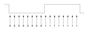
The receiver starts in an initial unsynchronised state. It continually samples the I/O line and shifts the value into a sample buffer containing the last16 values. After each sample, a check is made to see if the buffer contains a value that looks like a transition. At this point we are looking for the preamble, which is a string of zero-bits (encoded into a corresponding stream of 01 bit pairs). So, we want to detect the 0→1 transition, which marks the middle of each bit. The following diagram shows the ideal case:
In the above case, we have detected 8 zero-bit samples followed by 8 one-bit samples. But we may not see exactly this. For example, if the transmitter data clock is significantly faster than the receiver, the zero and one states in the signal will be shorter, and the adjacent states will leak into the sample bits at each end of the sample buffer. So, I do something like this:
if ((sample_bits & 0x1ff8) == 0x00f8)
    match = TRUE;
This excludes the three bits at each end of the sample from the comparison. Of course, if any of the other bits don’t match, then we don’t want to consider this sample as matching the transition.
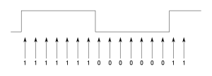
Once we think we have matched a transition, we step forward to where we expect the next bit transition to be; in this case we read in another 16 samples and see what we have received. While we think the preamble is being received, we know this should be another 0→1, but in general it could be either transition. Now, because the transmitter clock frequency could be different to receiver clock, the transition may not be exactly 16 samples later. This means that it may be offset from the centre of our sample buffer. For example:
In the above example, the transition is between the 7th and 8th bits, rather than where we expected it to be,between the 8th and 9th bits. So, we need to consider several bit mask patterns to cater for some likely offsets (say, plus or minus 3 samples from the centre). If a match is made at some offset from the centre, then it indicates that there is a significant clock difference between the transmitter and receiver. To ensure that this offset doesn’t keep accumulating, we need to adjust our sampling so that we look for the transition at a different interval. In the example above, because the transition was 1 bit early we reduce the sample counter to 15, for the next sample window. In this way, we continually adjust our sampling period to ensure that the transition stays in the middle of our window.
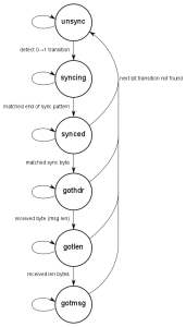
If at any time we fail to detect a valid transition in our sample buffer, we assume that we are dealing with noise or a corrupted message, and revert back to the initial state. Otherwise, we are now capable of recovering a bitstream from the receiver. This bitstream is shifted through an 8-bit “current byte” buffer. During the preamble period, we keep reading the bitstream until we encounter six zero-bits followed by two one-bits. This marks the end of the preamble and we move to the synchronised state.
When we enter the synchronised state, we are at a known point in the bitstream. The next thing we expect to receive is the header byte. We accumulate the next 8 bits from the bitstream and see if it matches the header byte. If there is no match, we return the to unsynchronised state, otherwise we are now ready to read in actual message data. As mentioned above, the message comprised a length byte, the message data and the CRC bytes. If we successfully read this in and is passes validation, the message is accepted and the system returns to the unsynchronised state.
In the code, the above algorithm is implemented in a simple Finite State Machine (FSM):
Implementation
The hardware for this was implemented using an Atmel ATtiny25 as the microcontroller on the sensor side. On the receiver side I used an Atmel ATmega48. The receiver is in the form of a small PCB that plugs onto the GPIO headers of a Raspberry Pi.
You can see the source code and circuit schematics for the whole thing on my GitHub repo:
https://github.com/rolfeb/proj-rf-sensor-network


